AC Motor Types Working Principle Single & Three Phase AC Motors
Three Phase Motor Power & Control Wiring Diagrams Three Phase Motor Connection Schematic, Power and Control Wiring Installation Diagrams. Star-Delta (Y-Δ) 3-phase Motor Starting Method by Automatic star-delta starter with Timer. Three Phase Motor Connection STAR/DELTA Without Timer - Power & Control Diagrams

3 Phase Motor Control Circuit Diagram Rig Electrician Training YouTube
On a three-phase motor the pole pattern has to be repeated for each phase. Therefore a 2=pole, 3-phase motor will have six poles. Figure 1. A 2-pole, 3-phase motor. Figure 2. A 4-pole, 3-phase motor. Figure 3. A 6-pole, 3-phase motor. Images from Basil Networks permanent magnet brushless motors page. This is worth a read as it shows the series.
AC Motor Types Working Principle Single & Three Phase AC Motors
Thus the three phase induction motor is: Self-starting. Less armature reaction and brush sparking because of the absence of commutators and brushes that may cause sparks. Robust in construction. Economical. Easier to maintain. Video - Working Principle of Three-Phase Induction Motor Want To Learn Faster? 🎓
3 Phase Power Circuit Diagram
The commutator (a split ring) and brushes (carbon contacts to the commutator) reverse the electric current every time the wire turns over, which keeps it rotating in the same direction. Before we move on to AC motors, let's quickly summarize what's going on here.
AC Motor Types Working Principle Single & Three Phase AC Motors
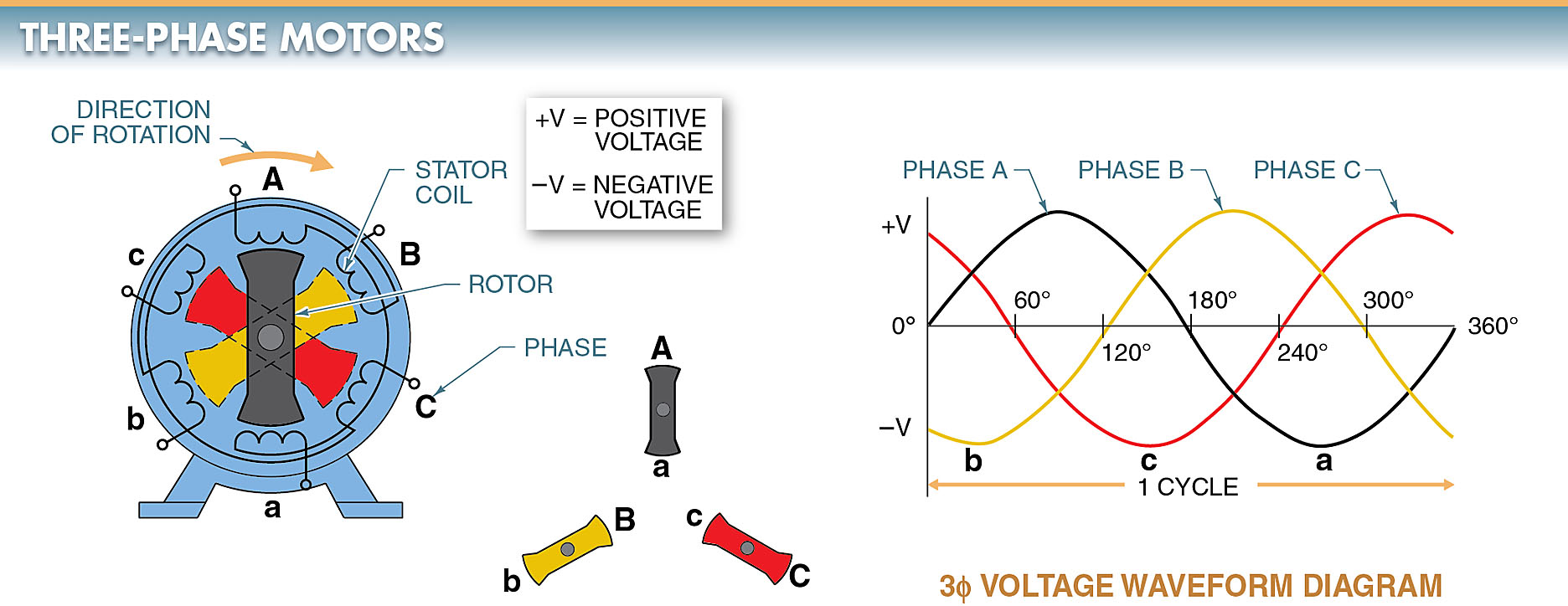
Three-phase electric power (abbreviated 3φ [1]) is a common type of alternating current (AC) used in electricity generation, transmission, and distribution. [2]
Running a Threephase electric motors on singlephase power
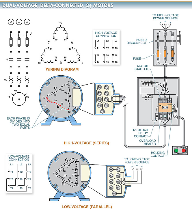
3 Phase AC Induction Motors INSTALLATION AND OPERATION MANUAL January 22, 2018 Indianapolis, Indiana (800) 866-7973. The following are the connection diagrams for STANDARD 3-phase general purpose 9-lead and 12-lead dual voltage motors. For all other connections such as two speed motors, 1-phase motors, alternate starting methods, etc.,.

3 Phase Motor Wiring Relationship Attachment Diagram Wiring23
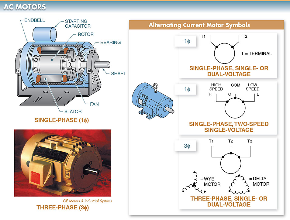
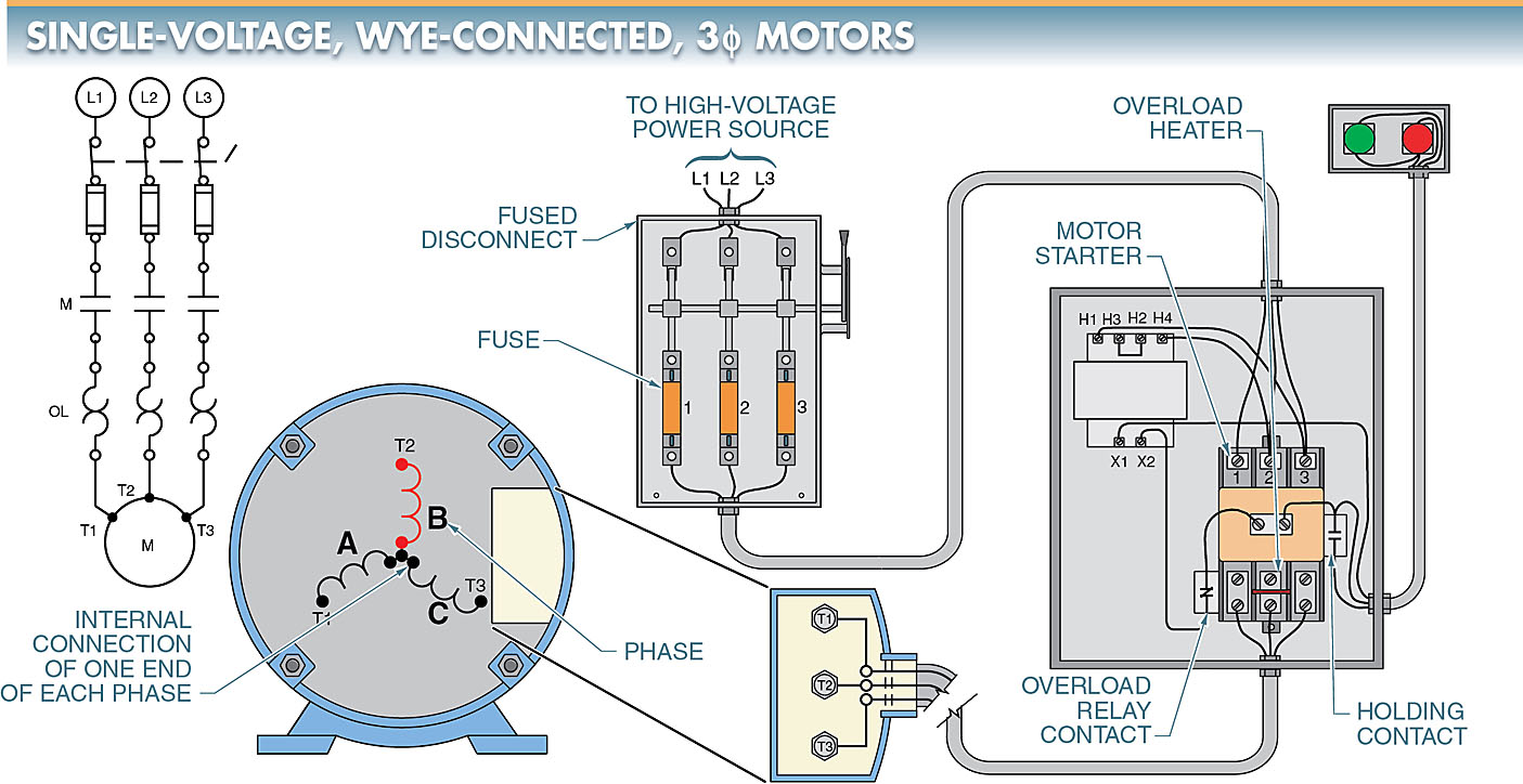
The most common type of three-phase motor is that which has nine labeled (and often colored) wires coming out of the box on the side. There are many motors with more or fewer wires, but nine is the most common. These nine-wire motors may be internally connected with either a Wye (star) or a Delta configuration, established by the manufacturer.
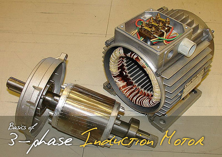
basicsofthreephaseacinductionmotor Engineering Tutorial
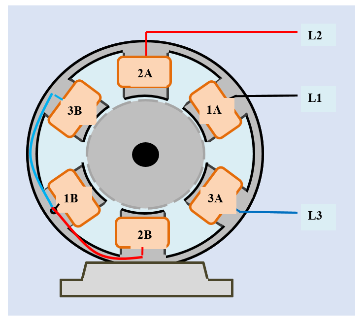
Here we see a winding diagram for a 3-phase AC induction motor or brushless PM motor (IPM), having 4 poles and 36 slots. This winding could in fact be used with any AC machine, including a synchronous reluctance motor or a wound-field synchronous motor or generator. In most respects it is a regular classical example, and the objective here is to review some of the features of the diagram and.
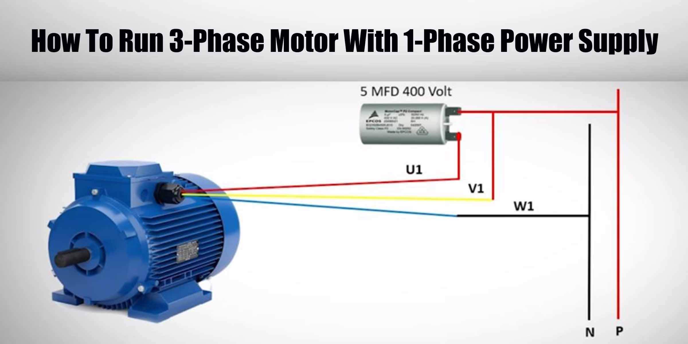
How To Run 3Phase Motor With 1Phase Power Supply Engineering
Diagram, Working & Types In this topic, you study Three Phase Induction Motor. Three Phase Induction Motor (Fig. 1) consists of a set of three phase windings distributed in slots around the stationary outer member called stator. The rotating member which is known as rotor also carries the other set of windings.

3 phase motor connection motor control circuit electrician training
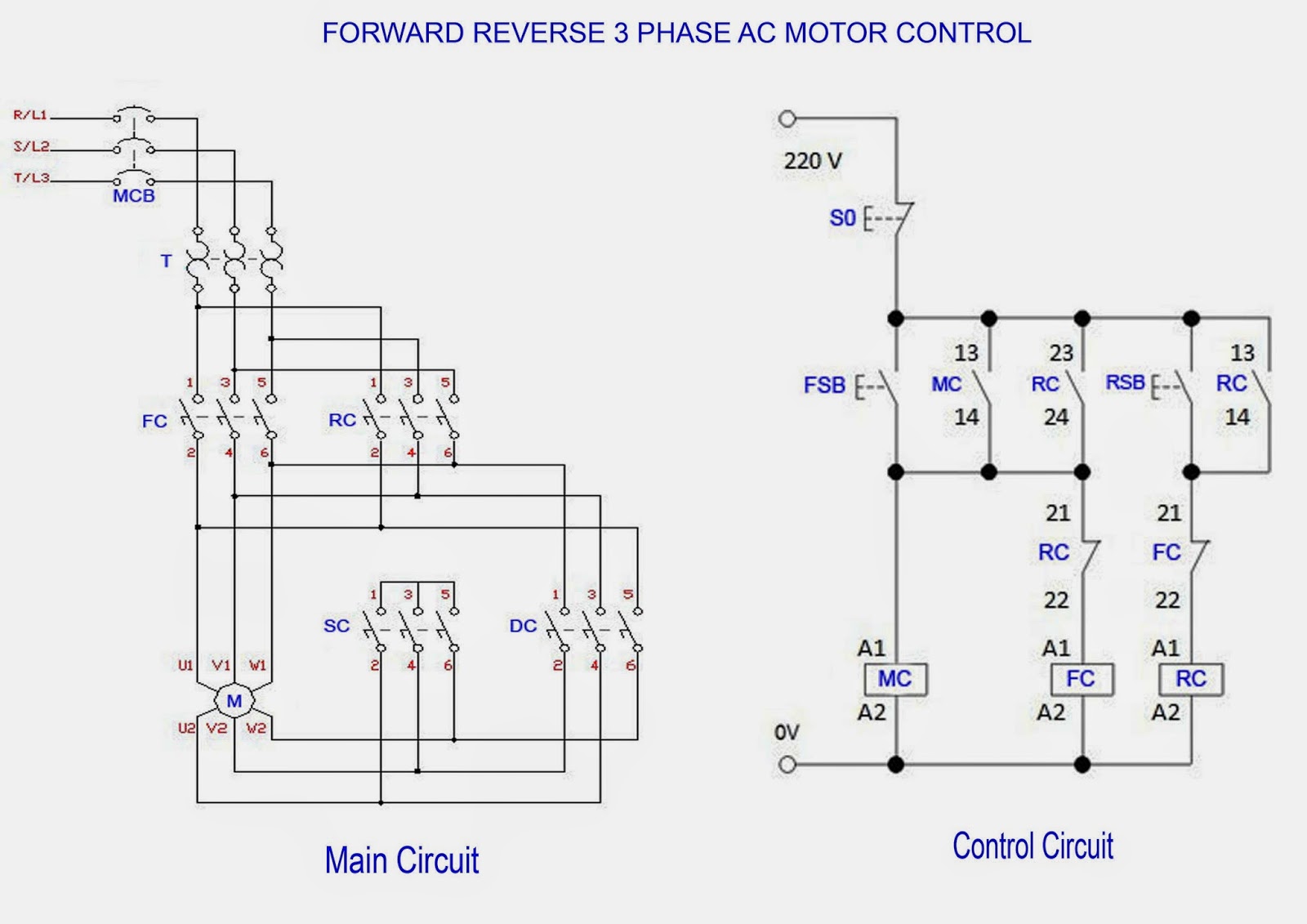
Main and auxiliary circuit diagrams of switching three-phase motors via contactor and directly In general, the graphic symbols in circuit diagrams are represented in a de-energized and mechanical non-operated state. Deviations from this rule mu be clearly indicated in the circuit diagrams.
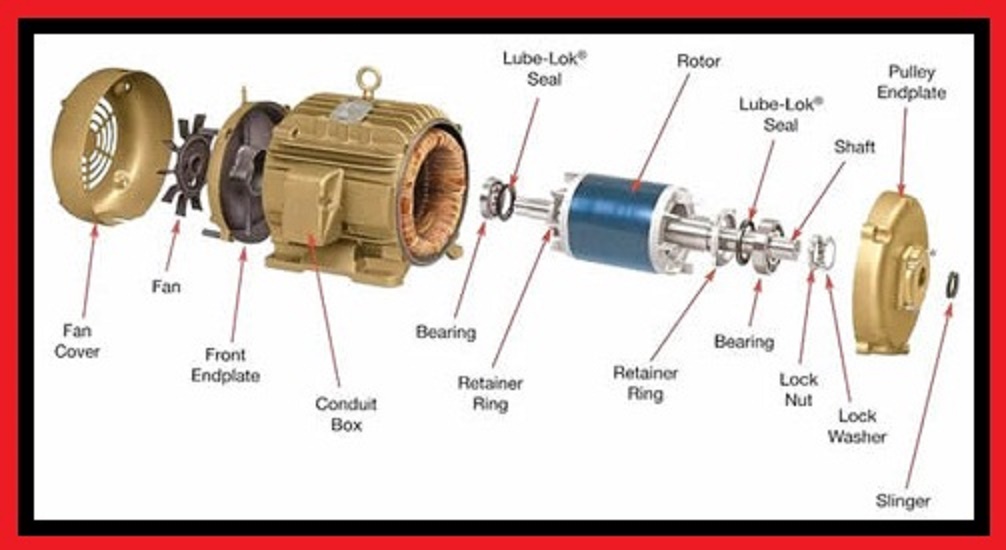
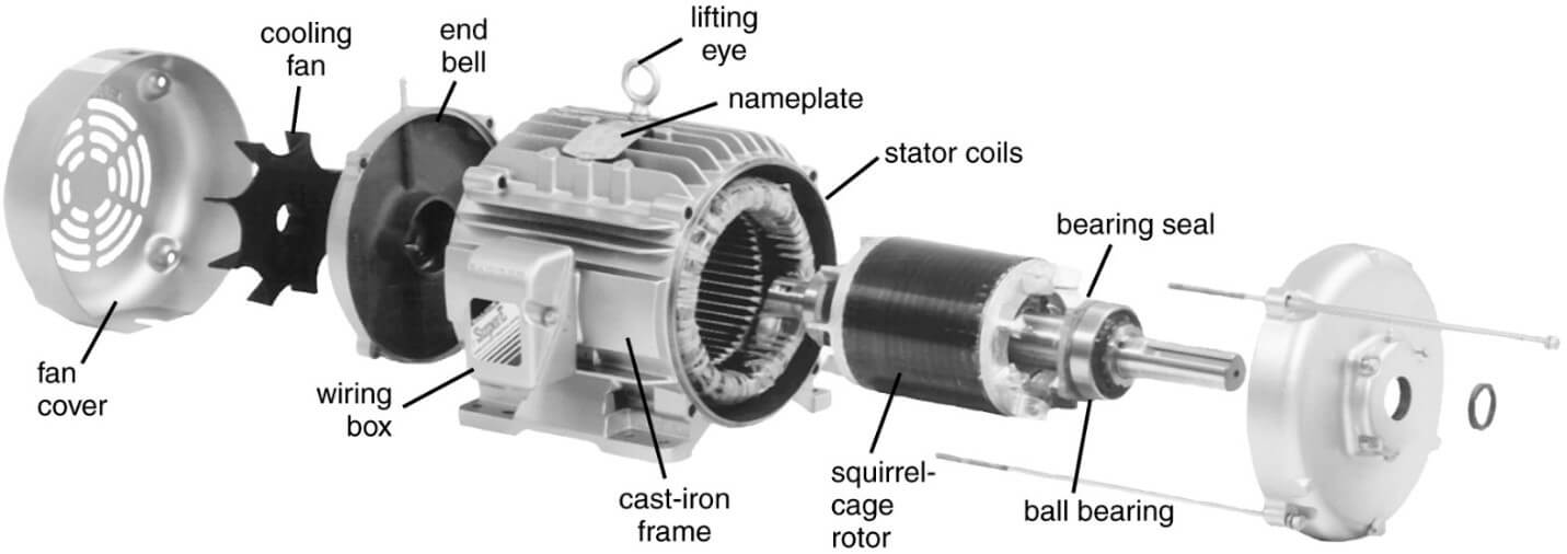
Electrical and Electronics Engineering Three Phase Motor Exploded View
The following line diagram illustrates how a normally open and a normally closed pushbutton might be connected to control a three-phase AC motor. In this example, a motor starter coil (M) is wired in series with a normally open, momentary Start pushbutton, a normally closed, momentary Stop pushbutton, and normally closed overload relay (OL.

How a 3 Phase Motor Control Circuit Works YouTube
Three-phase AC motors can be divided into three general types: squirrel-cage, wound-rotor and synchronous. Only the squirrel-cage rotor motors and the wound-rotor motors are induction motors. The rotor circuit in an induction motor does not have an external power supply.
AC Motor Types Working Principle Single & Three Phase AC Motors
A 3-phase motor works by harnessing three alternating currents to produce a rotating magnetic field, which, in turn, drives the motor's rotor and induces rotation. This design enhances efficiency and performance, making 3-phase motors suitable for a wide range of industrial applications.
ThreePhase AC Generator Working Electrical Academia
Physics Current Electricity AC Motor AC Motor An AC motor is an electric machine that converts alternating current into mechanical rotation. AC motor applications range from industrial bulk power conversion from electrical to mechanical to household small power conversion.
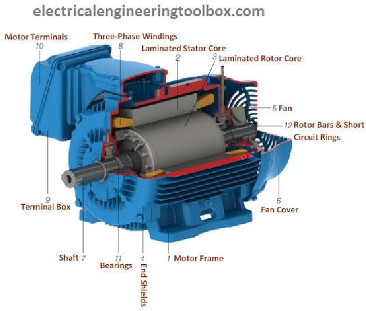
ThreePhase Induction Motor Construction Parts
In this tutorial, we will demonstrate the automatic star-delta (Y-Δ) starting method for 3-phase AC induction motors. This will include providing a schematic, power and control, PLC ladder, and wiring diagrams. We will also explain how the star-delta starter works and discuss its applications, as well as its advantages and disadvantages.

3 Phase Ac Motor Wiring Diagram
The three phase induction motor is the most widely used electrical motor.Almost 80% of the mechanical power used by industries is provided by three phase induction motors because of its simple and rugged construction, low cost, good operating characteristics, the absence of commutator and good speed regulation. In three phase induction motor, the power is transferred from stator to rotor.